Comparing O2 Combustion Trim Systems
The Problem
Efficient combustion is a goal for all energy users. Not only does efficient combustion save money, but it also prevents the generation of harmful emissions and can reduce service calls, equipment shutdowns and upset customers. The problem is that there has been no good system of combustion control (fuel-air-ratio control) for the commercial and small industrial user. While there are systems like Oxygen Trim, they are expensive and complicated, and often turned off because of the high maintenance cost.
A combustion control system controls the fuel-air ratio of a burner. The fuel-air ratio is generally defined in terms of excess air (%) or excess Oxygen (%). These terms are all inter-related and readings can be converted from one to the other. Flue gas analyzers read % Oxygen, but this is not a proportional relationship to the excess air, which is why these several terms are used.
The primary issue is that the fuel-air ratio, or excess air, changes with the normal operation of a burner. This is because burner combustion air fans deliver a constant volume of air, but as air temperature changes air density also changes, resulting in a different mass flow of air. For example, if a burner is operating at 20% excess air in the morning when the air temperature is 40°F, the excess air will drop to 11% in the afternoon when the air temperature increases to 85oF (all other factors being the same). Seasonal changes generate a much larger temperature swing, and often require seasonal adjustments to prevent the burner from having other problems. Smoking and high CO can occur when the temperature is high, and rumbling and high CO can occur when the temperature is too cold.
Learn how new technology controls excess air in response to changes in air density.
To better understand how air temperature plays a major role in the operation of a burner, consider the process of determining how the excess air level of a burner is determined.
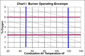
 The first step in the burner setup is to define the operating envelope. The envelope is a “Box” that defines the operating conditions of a burner. Two sides of the box are defined by the minimum and maximum excess air levels (or % Oxygen) of the burner operation. Typically, lower excess air levels result in smoking, high CO, and ultimately unburned fuel. At maximum excess air levels, the limit is defined by rumbling, instability, and high CO from too much excess air. The other two sides are defined by minimum and maximum combustion air temperature. With this operating envelope, a technician can determine how to setup the burner.
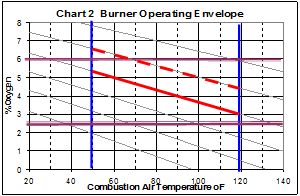
Chart I shows a typical operating envelope. The burner can operate from 2.5% O2 (12% excess air) to about 6% O2 (36% excess air). The air temperature varies from 50 to 120°F. The slanted lines indicate how the %O2 will vary with temperature. For example, if a burner is set up with the O2 at 4.5% when the combustion air temperature is 120°F, then when the combustion air temperature drops to 50°F, the O2 will be about 6.5%, which is “outside the box”, and the burner will probably start rumbling or have high CO due to the high excess air levels. This is illustrated by the dotted line in Chart 2.
 The correct tuning is shown as the solid line in Chart 2. It remains inside the operating envelope and is close to the lowest (most efficient) excess air with a reasonable safety margin. This safety margin is used to cover variations in barometric pressure, humidity and hysteresis. While each of these additional factors can impact the excess air, their impact is typically much smaller than air temperature.
Changes in air density cause the fuel-air ratio of a typical boiler-burner system to have a fluctuating fuel-air ratio. The combustion air fan is a constant volume device, and will always provide a constant volume of air to the burner. As air temperature changes, the air density changes, and will change the actual pounds of air, or mass flow provided to the burner. This is a well known problem, and service technicians compensate for these changes by simply increasing the excess air to make sure there will be enough air to always burn the fuel. If there is not enough air for complete combustion, there will be high levels of CO, smoke and /or unburned fuel.
This normal change in excess air makes it difficult to maintain an optimum efficiency. If the excess air is higher than needed, heat is lost because the excess air is heated to the stack temperature and that energy is lost to the environment. Air temperature is the largest factor that impacts the excess air change of a burner. A normal seasonal variation is about 60 to 80°F in a typical boiler room, but it can be much larger with ducted air or outside installations. A change from 120°F to 40°F in the combustion air temperature will result in an excess air change of about 16%. A change in barometric pressure from 30” to 29” is only a 3.4% change in excess air. Other changes affecting density, like humidity, have a smaller impact. The fuel properties are controlled by pressure regulators, limits on the HHV, and running the gas lines underground to maintain a constant temperature. This makes the change in combustion air temperature the largest variable in changes to the excess air level of a burner.
Past Fixes
The problem defined above is not a new problem and many people have worked to find solutions to regain lost efficiency and prevent problems related to high and low excess air operation. The most common solution is the Oxygen Trim system, which has been around for several decades. This product gained popularity from the oil embargo of the 1970’s, but lost credibility because of high cost and maintenance problems. They have resurfaced more recently when combined with parallel positioning controls, as they can be integrated into the parallel positioning control system, eliminating troublesome actuator assemblies.
Learn how new technology controls excess air in response to changes in air density.
The Oxygen Trim system uses a sensor to measure the excess oxygen in the flue gas, and will change the fuel or air flow to correct this level to match a pre-set level. The setup generally includes a combination of setpoints (for different firing rates and fuels) and actuator values that provide a known quantity of correction.
As previously stated, Oxygen Trim systems do work, but they have limitations:
- These systems are relatively expensive, especially when including the cost of the parallel positioning system and the additional startup time required.
- These systems must be field installed, which makes the startup more costly and more complex.
- There is a delay in the response of the system, due to the time required to allow the flue gas to pass through the boiler, sensor, and actuator system. At lower firing rates, this can be very long, and with a modulating boiler, the unit may not have time to correct the excess air before the firing rate changes.
- Maintenance costs are high, partly because the Oxygen cell can have a short life (it is in a hot dirty environment) and they require complicated retuning.
- Hysteresis, especially variations in hysteresis, can cause the unit to overshoot, making the result worse than no control at all, especially at lower rates. Many systems simply do not attempt to control at low rates because of this and the slow response of the system (time for flue gases to pass through the boiler).
Cost and complexity limits the applications where an Oxygen Trim system can be used, but it does provide an alternative means of correcting the excess air.
On the positive side, an Oxygen Trim system will correct for all conditions that may affect the excess air level, including changes in the fuel properties and fuel supply. In a large base loaded boiler, the Oxygen Trim system would provide very good control and fuel savings.
The New Control Solution
There is a new control system that uses a different approach to the problem, and is specifically designed to be very simple to apply, while eliminating the complex setup and maintenance issues. It does not have any contact with the flue gases, which are hot, dirty and wet. It makes the trade-off of not providing corrections for all variables with lower cost and simplicity.
This new control system is an air density trim system. It looks at the change in combustion air temperature and controls the excess air in response to this temperature change. The concept is to greatly simplify the control system as well as reduce the cost. Customers can get the majority of the savings with a small fraction of the cost, and without the problems of maintenance and setup of an oxygen trim system. The air density trim system uses a Variable Frequency Drive (VFD) to change the fan speed to correct the air flow and maintain a constant excess air rate. Because there is no site specific setup for this system, the control and VFD can be programmed and setup at the factory.
The control takes advantage of known relationships to make this correction in a very simple manner. The known relationships are:
- The air density will change in direct relationship to the (absolute) air temperature, as defined by the “Ideal Gas Law”. In other words, if the air temperature increased from 60°F to 100°F, the air density would decrease from .0765 lb/cf to 0.071 lb/cf, which is a 7.2% decrease in density.
- The fan is a constant volume device (Fan Laws). In the above example, if the initial fan volume were 100 CFM, then the flow at 100°F would also be 100 CFM. However, the mass delivery would change from 7.65 lb to 7.1 lb, a 7.2% decrease in mass flow.
- The volume generated by a fan is directly related to the speed of the fan (Fan Laws). If the fan was operating at 3000 RPM at 50°F, and then increased the speed to 3216 RPM (a 7.2% increase), the volume of air will increase to 107.2 CFM, and the new mass flow will be 7.65 lb. This is the same mass flow as the original operation, and we can see that this has exactly corrected for the change in air temperature.
 These relationships are built into the air density trim system in a manner that provides a “Fixed” relationship between the air temperature and the fan speed, so that a constant mass flow is provided at all times.
The fuel savings from the air density trim system will be similar to an Oxygen Trim system. The fuel savings comes from reduced excess air, where the additional air increases the dry gas and moisture loss. There is also some energy lost to the moisture in the excess air, but this is usually a very small amount.
The excess air also impacts the stack temperature of the boiler, where the higher the excess air, the higher the stack temperature will be. The primary reason is that a higher excess air level reduces the flame temperature, thereby reducing the heat transfer in the furnace and increasing the stack temperature. While some of the heat loss is recovered from higher mass flow in the convection pass, there is an overall loss of heat transfer. There is no exact relationship between excess air and stack temperature, but units with a relatively large amount of heat transfer surface (firetube boilers generally have 5 square feet per boiler HP) will have a small variation while others will have a large variation in stack temperature. Improving the excess air level will have the additional efficiency gain of a lower stack temperature.
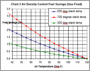
Chart 4 shows the estimated fuel savings using the air density trim system. At the highest normal combustion air temperature of 120°F, there is no difference between a unit with or without the air density trim system. The combustion air fan will be operating at full RPM to provide enough air to support combustion. As the air temperature drops, the air density trim system will slow down the fan to maintain a constant excess air, with a larger savings as the temperature continues to drop. The larger the temperature change, the larger the savings. The stack temperature is the other variable in fuel savings, where the higher the stack temperature, the higher the savings will be.
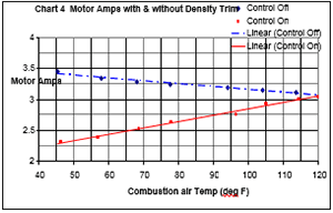
 In addition, the VFD will provide electrical savings, which is well documented for this type of control. Chart 5 shows a real example of how the electrical savings compare with a normal unit. Again, at the programmed high temperature, the fan will be at maximum speed and there will be no difference between the unit with or without air density trim system. As the air temperature drops, the air density trim system will reduce the fan speed, and therefore reduce the electrical usage. In a normal burner, the electrical use will increase with the drop in air temperature, as the higher air density requires more motor HP. Small reductions in fan speed will result in large electrical savings, because the energy used is based on the fan speed to the third power.
The air density trim system also provides some other advantages. The soft start provided by using a VFD allows the motor to ramp up to full speed over a period of several seconds, greatly reducing the inrush current at startup. Soft start reduces the heat buildup in the motor and can reduce the demand charge for the customer, as well as increase the life of the motor.
Operation of the motor at slower speeds also reduces the noise level of the burner. Most of the burner noise, just like the electrical energy, comes from the fan. Operating the fan at a slower speed reduces the noise level.
Conclusion
Air density trim provides similar fuel savings as Oxygen trim systems at a lower cost while eliminating the complex setup and maintenance issues. The air density trim system adjusts the burner fan speed to allow for changing air density caused by changing combustion air temperatures. By continually monitoring combustion air temperature and adjusting fan speed accordingly, the air density trim system provides fuel savings, electrical savings, increased boiler efficiency.


